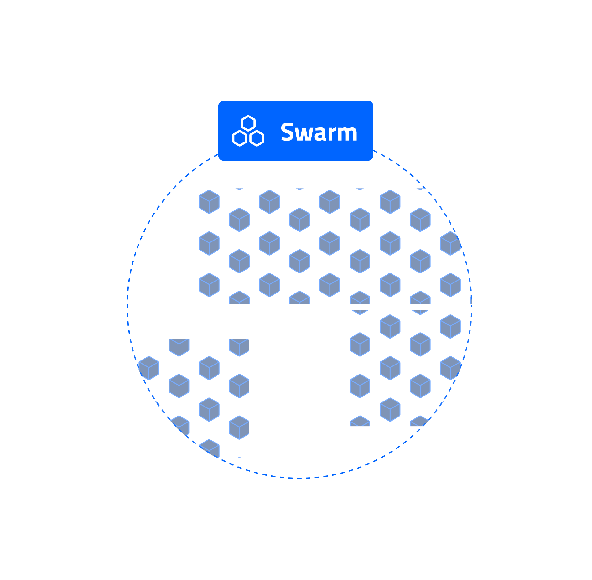
What is a Swarm?
A Swarm is a geo-distributed, modular, and scalable storage fabric composed of a dynamic collection of physical or virtual nodes. These nodes form a self-healing, fault-tolerant, and policy-driven object storage layer that powers Cubbit DS3.
At its core, a Swarm is responsible for the secure and redundant storage of objects. Objects are split, encrypted, and encoded into shards, which are then distributed across nodes to ensure durability, compliance, and performance. The placement and redundancy logic is governed by Redundancy Classes, enabling multi-level resilience at both the node and geographic level.
Swarms can be deployed in a wide range of topologies — from single-site setups to complex, multi-region infrastructures — allowing organizations to adapt storage policies to operational constraints, regulatory requirements, or performance goals.
Architecture
To deliver this level of flexibility and resilience, a Swarm is composed of several key building blocks:
- Nodes, which provide storage capacity
- Agents, which manage individual disks
- Rings, which organize agents by redundancy policies
- Redundancy Classes, which define data protection and distribution rules
- Nexuses, which group nodes by proximity or shared failure domains
The following sections explain each component and describe how they interact to deliver high-performance, fault-tolerant, distributed storage.
Nodes
Nodes are the fundamental infrastructure elements in a Swarm. They represent physical or virtual machines that contribute raw storage capacity to the system. A node may reside in a data center, at the edge, or in a virtualized cloud environment.
Each node connects to the Coordinator, which monitors its status, assigns roles, and orchestrates its participation in storage operations. Operators manually register nodes, which can be added incrementally to scale the system without downtime.
Agents
Agents are lightweight, containerized processes running on each Node. Each Agent manages a single disk and is responsible for:
- Handling encrypted data shards
- Performing upload and download operations
- Reporting disk health and telemetry
- Enforcing redundancy policies at the disk level
A Node typically hosts one or more agents (depending on how many disks it exposes), enabling precise control over storage allocation and fine-grained failure recovery. Because Agents operate at the disk level, they allow efficient disk lifecycle management and help minimize data loss in case of hardware issues.
Nexuses
A Nexus is a logical grouping of Nodes within the same physical or geographic fault domain — such as a data center, availability zone, or region. Nexuses are the fundamental units for enabling geo-distributed storage policies and disaster recovery.
Purpose of Nexuses
- Failure domain isolation: By spreading shards across multiple Nexuses, the system minimizes the risk that a localized incident (e.g., data center power outage) can compromise data availability.
- Data residency and compliance: Nexuses can be geo-fenced to specific regions or countries to meet regulatory requirements (e.g., GDPR, ISO, national sovereignty laws).
- Recovery performance: Local failures (e.g., a node or disk) are typically recoverable within the same Nexus, offering faster repair and less inter-site bandwidth usage.
Characteristics
Each Nexus contains a flexible number of Nodes. Nodes may be added to a Nexus dynamically over time. Nexuses are referenced by Redundancy Classes, which define the number needed to store or reconstruct data. Think of a Nexus as Cubbit's equivalent to an availability zone — a bounded, reliable fault domain used to distribute storage and optimize recoverability.
Redundancy Classes
Once Nodes are organized into Nexuses, Redundancy Classes (RCs) define how data is stored across those resources — both locally and geographically. A Redundancy Class is a policy that configures:
| Parameter | Description |
|---|---|
| Number of Nexuses required to reconstruct data | |
| Number of additional Nexuses for redundancy | |
| Number of Agents per Nexus required for local reconstruction | |
| Additional Agents per Nexus for node-level redundancy | |
| Max number of Agents per node (Anti-Affinity Group) |
Each RC results in a two-tier Reed-Solomon erasure coding scheme:
- Local Redundancy: Protects against disk or node failures within a Nexus.
- Geo Redundancy: Protects against site-wide failures across Nexuses.
- AAG Constraints: Ensure physical isolation of shards on separate hardware.
The size overhead introduced by the redundancy class is called ratio and is equal to
Example: Resilient Multi-site Setup
Configuration
This configuration requires:
- 5 Nexuses total (3 needed for data recovery + 2 redundant)
- 6 Agents per Nexus (4 + 2), each on a separate physical host
With this setup, the system can lose:
- Up to 2 entire Nexuses
- Up to 2 nodes per surviving Nexus ...with no data loss.
Example: Edge-optimized Configuration
Configuration
With this configuration:
- All data stays local to one Nexus.
- It can tolerate three node failures within the same site.
- Ideal for constrained, low-cost environments.
Why It Matters
Redundancy Classes allow Operators to:
- Fine-tune resilience vs. cost tradeoffs
- Define storage tiers for different Tenants or Projects
- Comply with geo-fencing, anti-affinity, and performance goals
- Evolve infrastructure without re-architecting the Swarm
Multiple RCs can coexist in the same Swarm — each backed by its own Rings, which we’ll cover next.
Rings
A Ring is a concrete instantiation of a Redundancy Class — a group of Agents that store and manage data according to a specific policy.
Each Ring:
- Implements one and only one Redundancy Class
- Contains a set of Agents across one or more Nexuses
- Acts as an independent unit of storage capacity
Ring Behavior
- Rings define the active set of Agents used to store new data.
- When a Ring nears capacity, a new Ring can be created for the same Redundancy Class.
- Agents may participate in multiple Rings, enabling multi-tenancy, hot/cold tiering, or isolated storage zones.
Rings make the Swarm modular and scalable: you can grow storage incrementally, optimize placement, and rebalance workloads over time without reconfiguring the whole system.
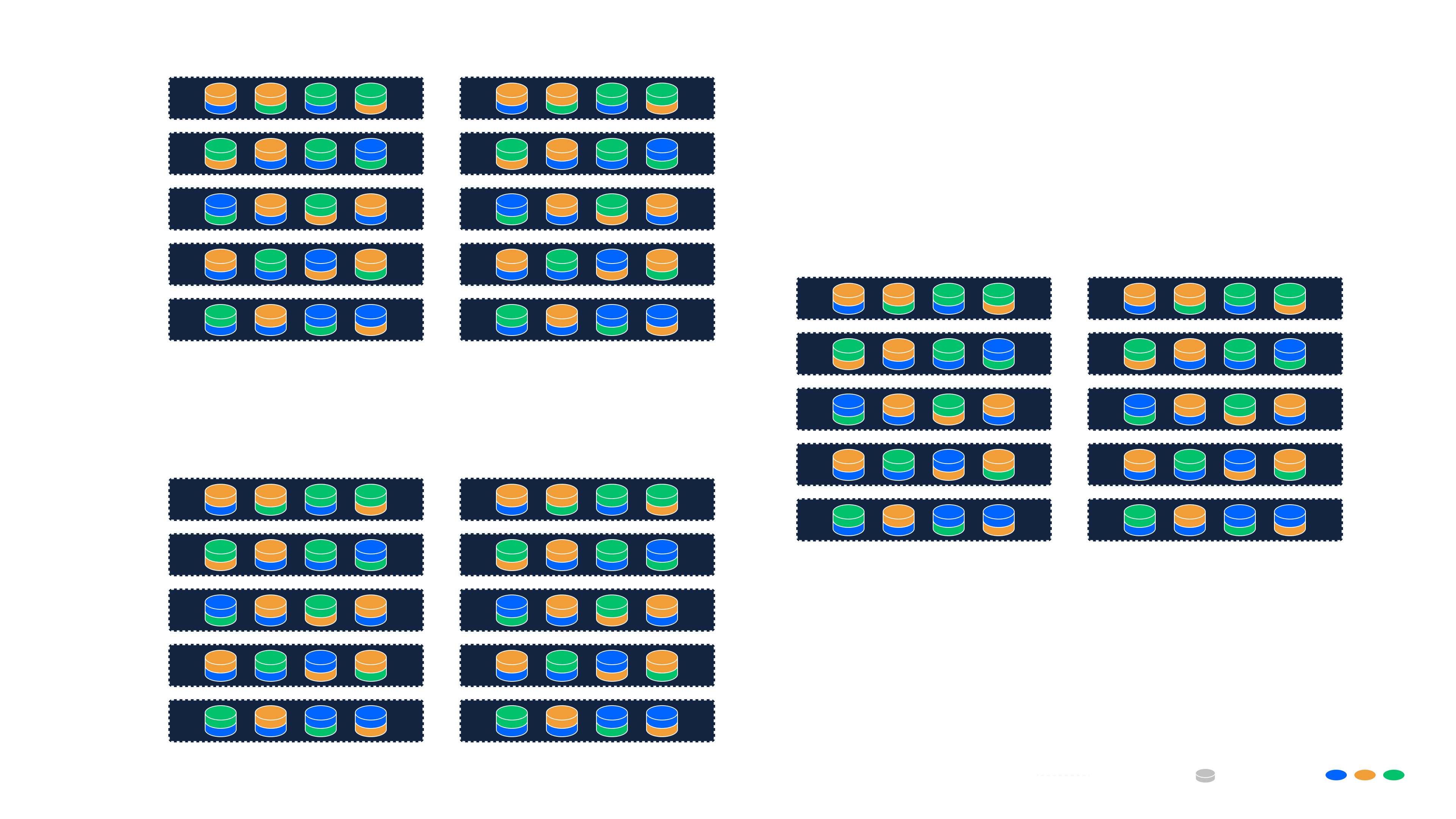
Example: Single-Site Deployment with Local Redundancy
This example describes a typical single-site deployment using 10 servers, each with eight disk drives (for a total of 80 disks). All servers run storage Agents, one per disk.
Redundancy Class Configuration
- (single Nexus deployment)
- (20 shards per object)
- (no more than two shards from a ring on the same physical server)
This Redundancy Class leads to the following outcomes:
- A Redundancy Factor of 1.25×: Each object is split into 16 data shards and 4 parity shards ( shards). Since only 16 shards are needed for recovery, the system achieves a 25% storage overhead for redundancy (= ).
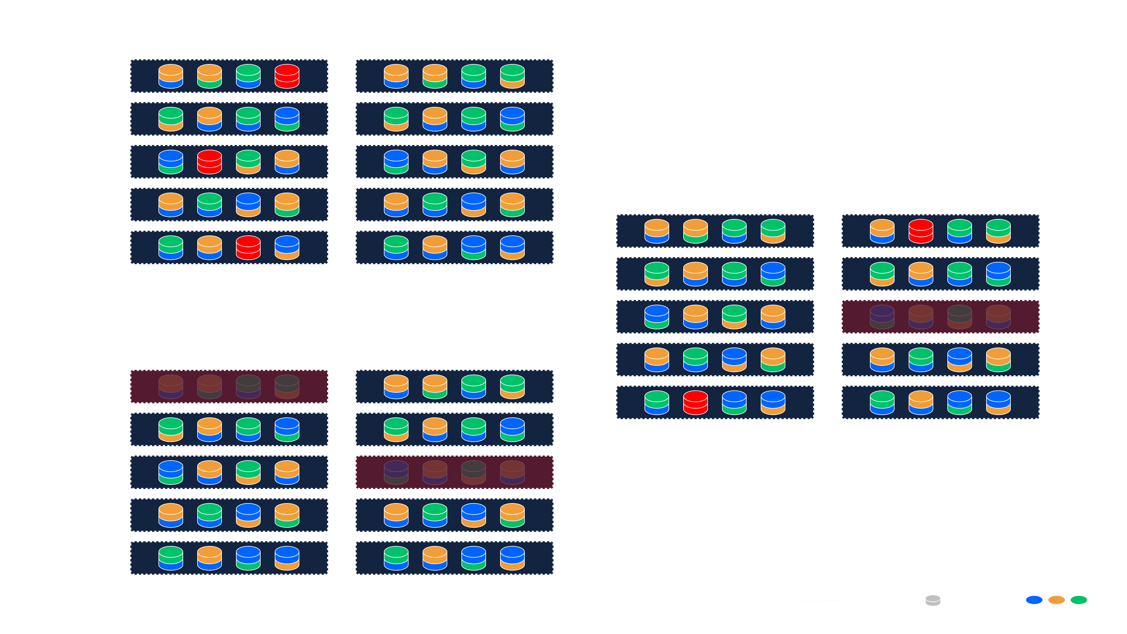
- Rings: The system can automatically or manually instantiate 4 independent Rings. These Rings can be visualized as four color-coded sets of 20 Agents each in the image below, spreading load and isolating capacity units.
Behavior
- Each of the 20 shards is stored on a different disk (Agent) within a Ring.
- Any 16 shards are sufficient to reconstruct the original object.
- The aag = 2 constraint ensures that no more than two shards from a Ring are stored on the same physical server.
- This means the system can tolerate the failure of up to 2 entire servers within a Ring without any data loss.
This configuration offers a robust and efficient architecture for enterprise on-premise deployments, with predictable fault tolerance and optimal resource utilization.
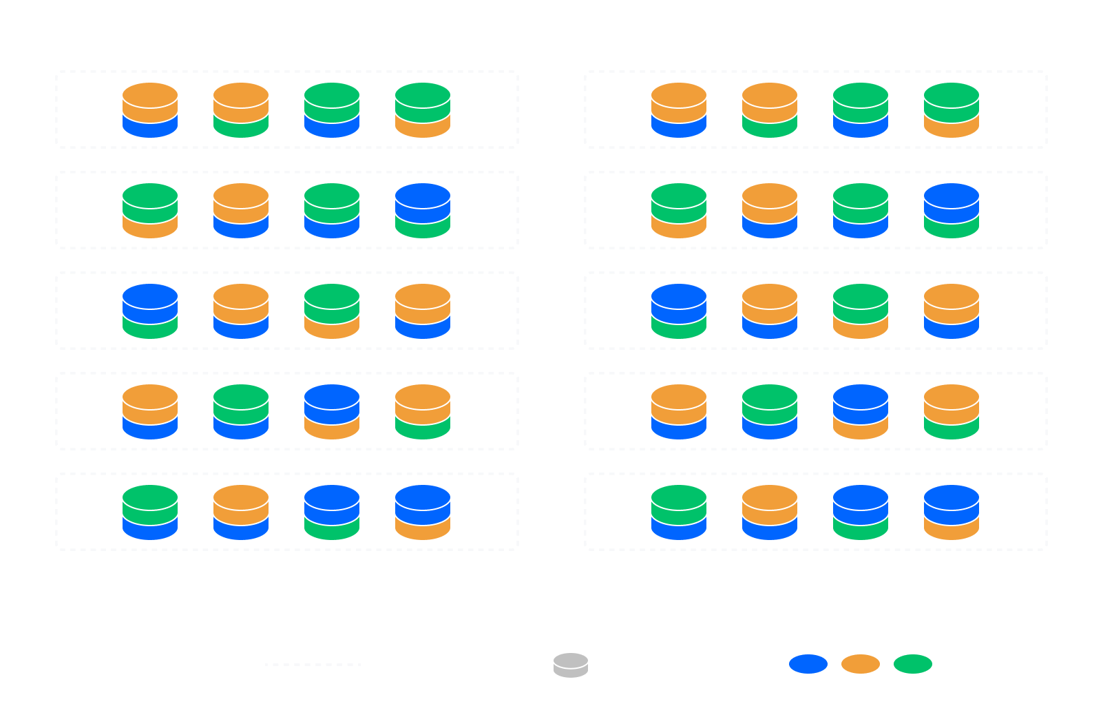
Example: multi-site deployment with geo-redundancy
In this example, we extend the single-site setup to a geo-redundant, multi-site deployment across three independent sites. The infrastructure follows the same local configuration (16 + 4 shards per object, AAG = 2) but introduces geographic-level fault tolerance.
Redundancy Class Configuration
- (data can be recovered from any 2 of 3 sites)
- (as example above)
Behavior
- Data is distributed across 3 Nexuses (one per site).
- Each site stores 20 shards (16 + 4) per object, following the local redundancy policy.
- Only two of the three sites are required to fully reconstruct any object—the third acts as a spare.
- This protects against full-site failures while maintaining fast local recovery from node or disk failures.
Fault Tolerance
This configuration can tolerate:
- Up to 1 entire site failure
- Up to 2 server failures per site
- Up to 4 disk failures per site
Redundancy Factor
- The local redundancy factor remains 1.25× (20 shards / 16 required).
- The geo redundancy factor adds an additional 1.5× overhead (3 sites / 2 required).
- The resulting combined redundancy factor is 1.875×:
Total Raw Capacity / Usable Capacity =
In other words, for every 1.875 TB of raw storage, you can expect 1 TB of usable capacity.
This setup strikes an excellent balance between high durability and efficient resource use. By mixing Nexuses and Rings, operators can achieve exceptional fault tolerance with a relatively modest increase in redundancy.
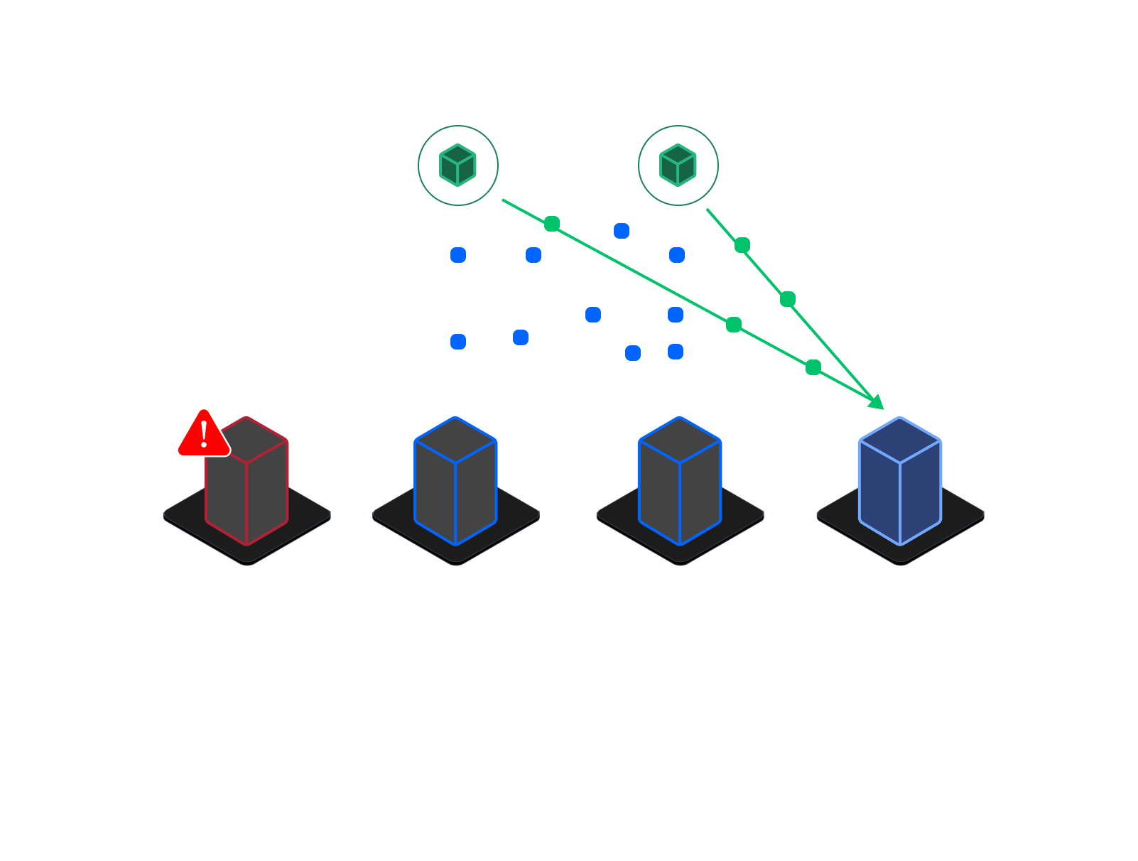
Self-healing and recovery
DS3 Swarms are designed to self-heal and recover automatically from localized hardware failures and large-scale site disruptions. Depending on the scope of the failure, recovery operations occur at two levels: local (intra-Nexus) and geographic (cross-Nexus).
Failure Detection
The Coordinator continuously monitors the health of all nodes, Agents, and Nexuses in real time. If a threshold is breached—such as a disk becoming unresponsive or a Nexus going offline—alerts are generated, and recovery workflows can be initiated either automatically or via API/user action.
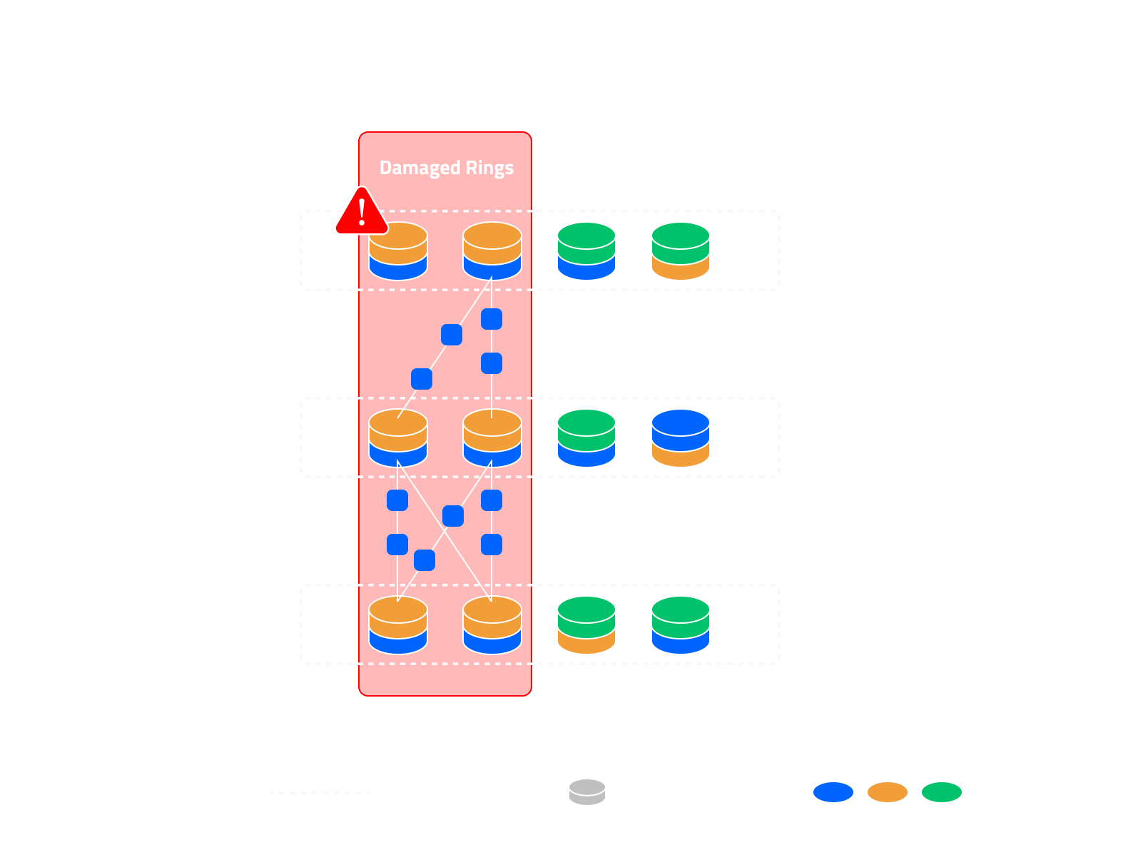
Local Recovery (Intra-Nexus)
When a node or disk fails within a Nexus:
- Failed components are replaced, and new Agents are deployed.
- Operators can initiate recovery via the web interface or DS3 API.
- Agents in the affected Ring establish peer-to-peer (P2P) connections with healthy Agents in the same Nexus.
- Missing shards are reconstructed using Reed-Solomon parity and redistributed to restore the original redundancy level.
This process restores system integrity without needing to access external Nexuses, minimizing bandwidth usage and optimizing recovery speed.
Geographic Recovery (Cross-Nexus)
When an entire Nexus becomes unavailable:
- A new Nexus is created by provisioning and registering replacement nodes.
- DS3 Gateways assist recovery by downloading enough data shards from the remaining Nexuses to reconstruct the missing segments.
- Redundancy layers are inverted and re-encoded to generate the required shards.
- These are then distributed to the new Nexus, restoring redundancy and capacity.
This ensures that even large-scale regional outages do not compromise data durability or availability.